
VACUUM PUMP USER MANUAL
SECTION A
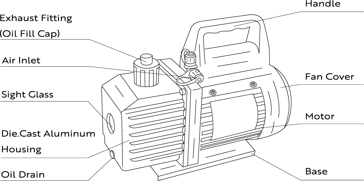
Pump Components
SECTION B
Operating Manual
1. Before using your vacuum pump
In all cases, motors are designed for operating voltages plusor minus 10% of the normal rating.Single-voltagemotors are supplied fully connected and ready to operate.
(1)Check to be sure the voltage and frequency at the outlet match the specifications on the pump motor decal. Check the ON-OFF switch to be sure it is in the OFF position before you plug the pump into an outlet. Remove and discard the exhaust cap from the end of the pump’s handle.
(2)The pump is shipped without oil in the reservoir. Beforestarting the pump, fill it with oil. Remove the exhaustfitting cap and add oil until oil just shows at the bottom ofthe sight glass. The approximate oil capacity of the pump is 180-800 ml(reference the technical data).
(3)Replace the exhaust fitting cap and remove the cap from one of the inlet ports, Turn the motor switch to ON. whenthe pump runs smoothly, replace the cap on the inlet port.This may take from two to 30 seconds, depending on the ambient temperature. After the pump runs for approximately one minute, check the sight glass for the proper oil level. The level should be even with the sight glass oil level line.Add oil if necessary.
Note: When the pump is running, the oil level should be even with the line on the sight glass. Underfilling will result in poor vacuum performance.Overfilling can result in oil blowing from the exhaust.
2. To shut down your pump after use
To help prolong pump life and promote easy starting. Follow these procedures for the shutdown.
(1)Close the manifold valve between the pump and the system.
(2)Remove the hose from the pump inlet.
(3) Cap the inlet port to prevent any contamination or loose particles from entering the port.
SECTION C
To Maintain Your High Vacuum Pump
1. Vacuum pump oil
The condition and type of oil used in any high vacuum pump are extremely important in determining the ultimate attainable vacuum.We recommend the use of High Vacuum PumpOil. This oil has been specifically blended to maintain maximum viscosity at normal running temperatures and to improve cold weather starts.
2. Oil change procedure
(1)Be sure the pump is warmed up.
(2)Remove the OlL DRAlN cap. Drain the contaminated oil into a suitable container and dispose of it properly. Oil canbe forced from the pump by opening the inlet and partially blocking the exhaust with a cloth while the pump is running. Do not operate the pump for more than 20 seconds using this method.
(3)When the flow of oil has stopped,tilt the pump forward to drain any residual oil.
(4)Replace the OlL DRAlN cap.Remove the exhaust fitting and fill the reservoir with new vacuum pump oil until the oil just shows at the bottom of the sight glass.The approximate oil capacity of the pump is 180-800 ml(reference the technical data).
(5)Be sure the inlet ports are capped, then turn on the pump. Allow it to run for one minute then, check the oil level. lf the oil is below the sight glass OlL LEVEL line, add oil slowly (with the pump running) until the oil reaches the OlL LEVEL line.Replace the exhaust fitting, making sure the inlet is capped and the drain cap is tight.
(6)a) lf the oil is badly contaminated with sludge that formswhen water is allowed to collect in the oil, you may need to remove the oil reservoir cover and wipe it out.b) Another method of dealing with heavily contaminated oil is to force the oil from the pump reservoir. To do this,allow the pump to run until it is warmed up. While the pump is still running, remove the oil drain cap. Slightly restrict the exhaust. This will backpressure the oil reservoir and force the oil from it, resulting in more contamination.When the oil ceases to flow, turn off the pump.Repeat this procedure as required until the contaminant is removed.
Replace the OIL DRAlN cap and refill the reservoir to theproper level with fresh pump oil.
SECTION D
Troubleshooting Guide
Your pump has been for dependable use and a long life. lf something should go wrong, the following guide will help you get the pump back into service as quickly as possible.If disassembly of the pump is required, please check your warranty .The warranty may be voided by misuse or customertampering, which results in the pump being inoperable.
1.Failure to start
Check the line voltage.The pump needs to start at +10% line voltage (loaded) at:32°F,At extremes, switching between the start and run windings may occur.
2. Oil leakage
(1) Be sure the oil is not a residual accumulation from spillage, etc.
(2)lf leakage exists, the module cover gasket or the shaft seal may need replacing.lf leakage exists in the area of the oildrain plug, you may need to reseal the plug using a commercial pipe thread sealer.
3. Failure to pull a good vacuum
(1) Be sure the vacuum gauge and all connections are in good condition and leak-free. You can confirm leakage by monitoring the vacuum with a thermistor gauge while applying vacuum pump oil at connections or suspected leak points.The vacuum will improve briefly while the oil seals the leak.
(2)Be sure the pump oil is clean.A badly contaminated pump may require several oil flushes.
(3)Be sure the oil is at the proper level. For maximum pump operation,the oil must be even with OlL LEVEL line on the sight glass when the pump is running. Do not overfill. Operating temperatures will cause the oil to expand, so it will appear at a higher level than when the pump is not running.To check the oil level, start the pump with the inlet capped,Check the oil level in the sight glass. Add oil if necessary.
SECTION E
Technical Parameter
Single Stage Vacuum Pump
Model |
VP135 |
Voltage |
110V~/60Hz |
Free Air Displacement(CFM ) |
4 |
Free Air Displacement(L/min) |
114 |
Ultimate Partial Pressure(Pa) |
5 |
Vacuum Total Pressure(Micron) |
150 |
Motor |
1/3 |
Intake Fitting |
1/4’’SAE & 1/2’’Acme |
Oil Capacity(ml) |
350 |
Dimensions(mm) |
278*119*216 |
Net Weight(kg) |
6 |
SECTION F
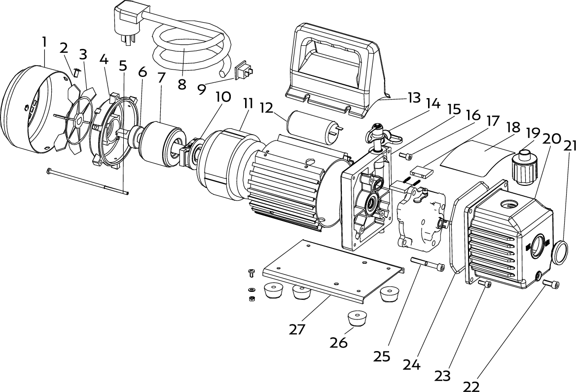
Exploded Drawing
1 |
Fan cover |
10 |
Centrifugal switch |
19 |
Exhaust fiting |
2 |
Cross screw |
11 |
Motor stator |
20 |
Die cast aluminum housing |
3 |
Fan |
12 |
Capacitor |
21 |
Sight glass |
4 |
Motor cover |
13 |
Handle |
22 |
Oil drain cap |
5 |
Cross screw |
14 |
Inlet fitting |
23 |
Screw |
6 |
Bearing |
15 |
Trestle |
24 |
Seal |
7 |
Motor rotor |
16 |
Screw |
25 |
Scren |
8 |
Power supply cords |
17 |
Rotary-vane |
26 |
Rubber foot |
9 |
Power switch |
18 |
Cap board |
27 |
Base |
SECTION G
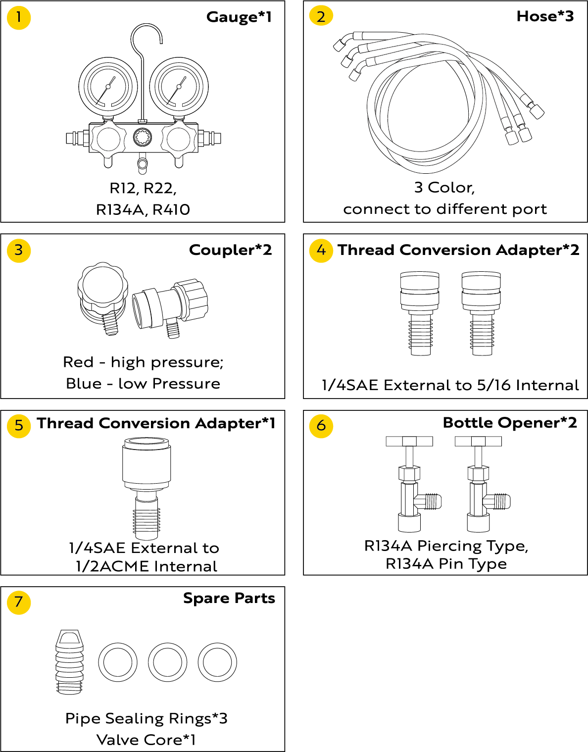
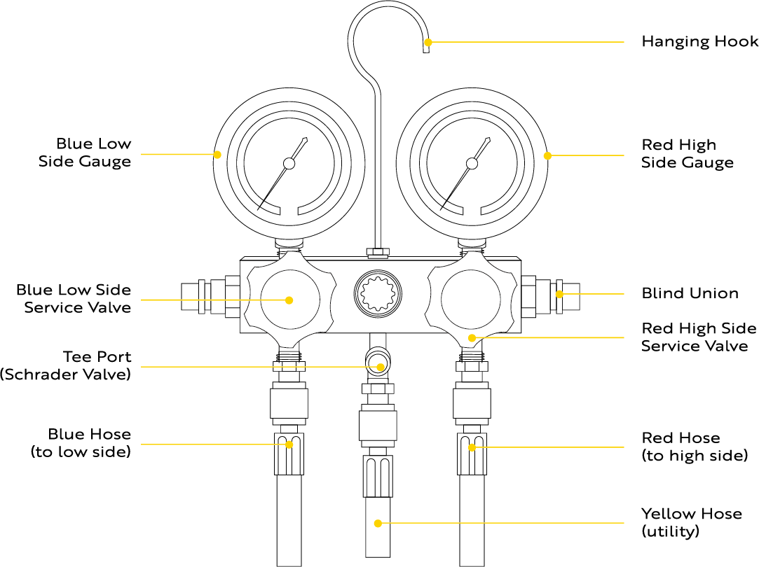
Manifold Gauge Set Instructions
Parts List
Operating Instructions
Schematic of gauge manifold installation on an external drive compressor with valves.A -Manifold Suction Valve. B - Manifold Discharge Valve.C-Compressor Discharge Service Valve (DSV).D-Compressor Suction Service Valve(SSV).E-Service Opening.1-Purging.2-Charging or Adding Oil.3-Bypassing.4-Gauge Reading. 5. Both manifold valves are turned all the way in.The system is pumping vapor, and both low- and high-side pressure readings are being displayed.
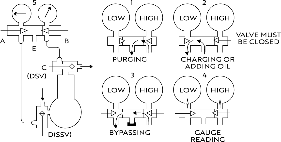
Lines from the manifold are attached to the SSV at D and should be left one to two turns loose, while the line to the DSV should be tightened.Then open both of the manifold valves at A and B 1/4 turn to 1/2 turn and cap the middle opening, E.
Now turn the (DSV) C stem in 1'8 to 1/4 turn for just a moment (crack the valve). A surge of high-pressure refrigerant will then rush through the lines and the manifold and purge to the atmosphere at the loose connection at D the SSV. This connection may then be tightened. Purging is necessary to remove air and moisture from the manifold andlines.
NOTE: Purging must be held to a minimum to avoid damage to the atmosphere.
Carefully test for leaks while the manifold and its lines are under high pressure.Correct any leak immediately.Various service and testing operations may be performed after the testing manifold has been installed:
-
Observe operating pressures by:
Closing valve A by turning all the way in. Closing valve B by turning. Cracking open back seat of valve C. Cracking open the back seat of valve D.
 -
Charge refrigerant into the system by:
Connecting the refrigerant cylinder to E (vapor only). Opening valve A. Closing valve B. Closing the front seat of valve D slowly.
Connecting the refrigerant cylinder to E(vapor only). -
Purge the condenser by:
Closing valve A. Closing valve B. Cracking open valve C. -
Charge liquid refrigerant into the high side by:
Connecting the refrigerant cylinder to E. Closing valve A. Opening valve B. Mid-positioning valve C. -
Build up pressure on the low side for control settings or to test for leaks by:
Sealing E with a seal cap. Opening valve A. Close valve C.
SECTION H
Warranty
The VIVOHOME warranty program is our commitment to you.We are committed to providing you with a high-quality product that meets your needs and expectations. To demonstrate our confidence in the durability and performance of ourproducts, we offer the following warranty.
WARRANTY COVERAGE
This warranty program applies to any orders, purchases,receipts, or use of any products sold by VIVOHOME and isvalid for a period of l year from the date of purchase. However, please note that this warranty period is only valid for the original order.lf you receive a replacement order during the warranty period, it will not include a separate warranty period.
WARRANTY EXCLUSIONS
This warranty does not cover damage resulting from misuseaccident,unauthorized modification, or any other circum-stances not directly related to the manufacturing and design of the product, including but not limited to:
-
Parts lost during use.
-
Normal wear and tear of products or parts.
-
Incorrect installation (such as using the wrong voltage) orassembly.
-
Exceeding the bearing capacity of the product.
-
Use under extremely harsh conditions.
-
lmproper cleaning or maintenance.
-
Damage caused by any reason other than the intendeduse of the product.
-
Indirect loss or damage caused by the product.
HOW TO MAKE A WARRANTY CLAIM
lf you find any defects that affect the use of the product or ifthe product stops working and cannot be repaired during the warranty period, please contact our customer service team at our email or via Amazon & app’s direct messaging service as soon as possible. Provide the following information to expedite the process:
-
Order number
-
lmages and/or videos illustrating the issue
-
A detailed description of the problem
VIVOHOME will provide technical support, replacement,refund, or other solutions based on the nature of the issue. lf you wish to return the original package for any reason, please contact us for confirmation before proceeding. You can expect to receive aresponse within 48 hours.
Thank you for choosing VIVOHOME. We are committed to ensuring the quality and satisfaction of your purchase. lf you have any questions or need assistance, please do not hesitate to contact our customer service team.
FAQS
Q: Can it be used for automotive applications?
A: Yes. This vacuum pump is suitable for automotive applications, as it is designed for tasks such as recharging AC units and is compatible with R134a, R12, R22, R502, and R410a systems.
Q: Can it be used for A2L refrigerants?
A: No. The product is not compatible with A2L、A2 or A3 refrigerants.
Q: What maintenance does it require?
A: Regular maintenance for this vacuum pump includes monitoring oil levels and quality through the oil sight glass, and performing timely oil changes via the drain valve.
Q: Does it come with a carrying case?
A: Yes. It does come with a carrying case.
Q: Is it made for professional use?
A: Yes. It is designed for personal and professional use, featuring a durable die-cast aluminum housing and a composite anti-slip rubber base.
Q: What is the noise level of this vacuum pump?
A: The noise level is typically between 65 and 70 dB during normal operation.
Q: What is the weight of the vacuum pump?
A: The item weight of the vacuum pump is 11.5 pounds.The net weight of the kit is 17.6 pounds.
Q: What is the power source for this vacuum pump?
A: The vacuum pump runs on 110V AC power.
Q: Is this vacuum pump easy to use for beginners?
A: Yes. Customers generally find this vacuum pump easy to use, especially for beginners. The product comes with illustrated instructions for an easy setup process. Additionally, several customers have successfully used the vacuum pump for tasks such as recharging AC units and installing mini-splits, even with limited prior experience.
Q: Does it come with a user manual?
A: Yes. It does come with a user manual.
Troubleshooting
1.Pump Body Fails to Start or Motor Runs Unstably
Causes:
Abnormal power supply voltage, capacitor failure, detachment of connectors, and excessive pump head load.
Recommendations:
1. Use stable power source and ensure that the plug and wiring are in good contact.
2. Check the capacitor, switch, and ensure the connecting wires are firmly attached.
3. Start the pump with the air intake open.
4. If excessive water vapor intake has caused the pump chamber rust, rotate the rotor blades counterclockwise with a flat-head screwdriver.
5. Operate the pump within an ambient temperature range of 5-40℃. At low temperatures, the pump oil may crystallize; under high-temperature conditions, multiple startup attempts may be required.
2. Slow Pumping Speed, Unable to Achieve Expected Vacuum Level
Causes:
1. Contaminated pump oil or incorrect oil level.
2. Air leakage or poor sealing at interfaces or hoses.
Recommendations:
1. Regularly replace with clean vacuum pump oil and ensure the oil level is near the middle of the sight glass (slightly higher when the oil is hot).
2. Check the sealing of all interfaces, especially ensuring the integrity of the sealing rings. Check whether there are impurities adhering to the exhaust valve plate.
3. Oil Leakage (Oil Spray) from Pump Body, with Oil Escaping from the Sight Glass or Bottom Valve
Causes:
1. Excessive oil level.
2. Aging of sealing rings or poor assembly connection leading to leakage.
3. The bottom oil drain valve (oil mist separator) is not reinstalled or tightened, or its accumulated dirt has not been cleaned.
Recommendations:
1. Adjust the oil level to avoid overfilling.
2. Always keep the pump level during the operation to prevent oil overflow caused by tilting. After adding oil, reattach the oil mist filter and clean it if it becomes too dirty.
4. Inaccurate Pressure Fluctuations on the Gauge Set, Hose Leakage, or Air Ejection at Interfaces
Causes:
1. Damaged hoses, poor sealing of connectors, or loose adjustment knobs on the gauge manifold.
2. Calibration error or damage to the gauge head.
Recommendations:
1. Check the condition of the hoses regularly. Use the finger-pressure method or observe hose expansion to determine if there is air leakage.
2. Tighten the connectors or replace the sealing rings to prevent the top nuts from loosening.
3. If the gauge itself provides inaccurate readings, consider adjusting it with a flat-head screwdriver or replacing it with a high-quality gauge head.
5. Leak Detector Error: Insensitive, False Alarms, or Malfunction
Causes:
1. Improper operation or failure to install four batteries.
2. Insufficient power or aging of the detection head.
Recommendations:
1. Check if all batteries are properly installed. After turning on the detector in a well-ventilated environment for a few minutes, repeatedly confirm leak points using both low and high sensitivity settings.
2. Replace the batteries.
3. Do not rely solely on one tool; use a combination of methods such as listening, smelling, and adding soapy solution to determine if there is a leak.